Principe
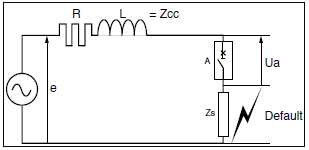
Note : Consider the minimum circuit opposite, where:
Ua : arc voltage created when the contacts of circuit-breaker A open
Zs : load, point of appearance of fault
Zcc : short-circuit impedance
i : current flowing in the mesh
e : emf when the short-circuit appears
Note : For a full short-circuit, we have the following equations:
E =R.i + L.di/dt + Ua, where E is the source voltage.
R.i can be considered to be negligible compared with L.di/dt:
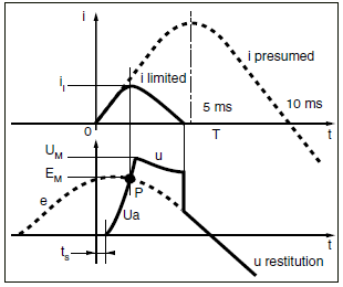
e = L.di/dt + Ua , thus limitation achieved more easily and quick decrease of Ic
When di/dt = 0, current i reaches its maximum value (= peak value), i.e. for Ua = e.
Fundamental :
See the interpretation in the graphs opposite, where ts is the time when voltage Ua appears, i.e. in the circuit-breaker case, when the contacts open.
In short, limitation will be correct when: Ua max. = UM > EM (of source)