
4. Connexion
The size of the wire depends on the current that it will carry. Usually, the cross section of the wire is 0.75 mm2 for the control circuit and 1.5 mm2 for the Power circuit. The size should be adapted to the current.

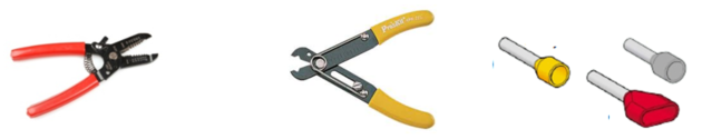
Advice : 4.1. Preparation of the wires:
• Set up the stripping plier to prevent to cut the wire or strands. • Remove the right length of insulation. • Slight twist of the strand wires. • The wire ends should have lugs to procure a good connection. The ferrule is clamped with dedicated tools. If the terminal is a spring type, lugs are not required. • Prevent to put strand outside the connector |  |
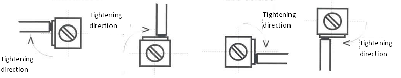
Advice : 4.2. Connexion to terminal
The position of the wire is important. The wire must be place according to the tightening direction of the connector:
• If there is two wire, place them on both sides of the terminal
• Note that two wire maximum must be connected to one terminal.
Advice : 4.3. Wiring rules
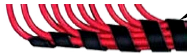
Regarding the wiring in raceway, the following rules must be followed: • Wire the power circuit before the control circuit. • For the control circuit: wire first the coil return (A2 terminals) then the button box, then the cabinet door and finally the mesh. • The bridge between two terminals should be run through the raceway. • The length of the wire should be enough to shape it. • Wire must come perpendicularly to the device or terminal • Wire terminal block from left to right and from top to bottom. • For a comb wiring, wire must be parallel | 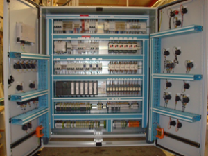 |
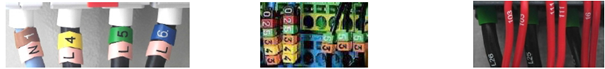
 | • The link to the loads, sensors should be made by cables. • The identification of the wire is given by the equipotential number on the diagram. This identification can be letters, numbers or both. The identification is made with ring, clips or direct printing. • Check the tightening. |
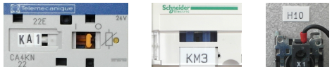
• All devices should be marked with specific tag.
Advice : 4.4. Wiring procedure
• Check with Multimeter the state of the contact
• Wiring the horizontal connection then each load.
• Mark each wire when it is out in place. Reading from bottom to top or left to right.
• Identification must be at 5 to 10 mm from the terminal.
• Tick on the diagram the wire put in place.


