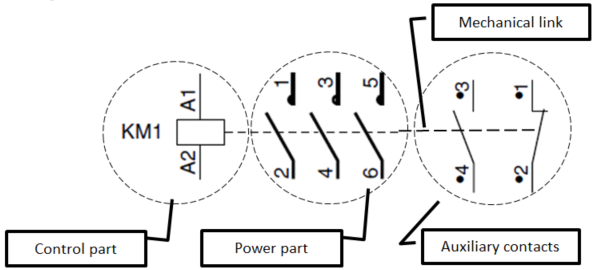
3. Symbolization of devices
Note :

Method : • Main contacts: Power circuit
o From 0 (control device) to 4 power contacts.
o Always represented together, they are drawn in solid line
Method : • Auxiliary contacts: Control circuit
o From 0 to 5 contacts, more with the use of add
o Ungrouped, drawn in fine line
o 2 types: Normally Open (NO), Normally Closed (NC)
o Mechanically linked to the control part they indicate the state of the device. By this, the state of a device can be used in a control circuit.
Method : • Control part (control of the contacts)
o Manual: drawn on the contact's left side.
o Electric (coil) load of the control circuit
Method : • Mechanical link:
o Partially drawn if it disturbs the reading of the electrical diagram.


