
Simplified method 1: Resistive loop
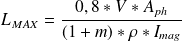
This method consists on the calculation of the resistance of the wire and checking the length of the cable is below the maximum length given by the formula: {
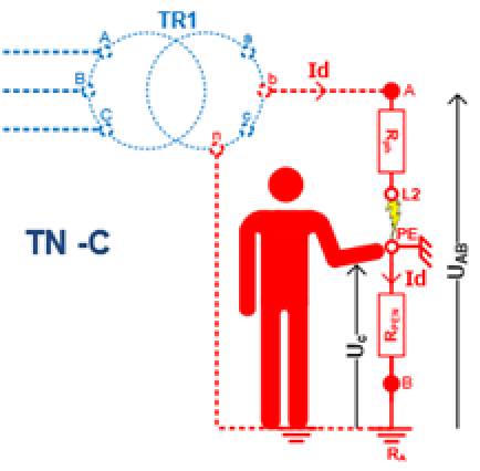
To take in account the transformer, the voltage supplying the loop is taken as 80% of the rated value.
|  |


Note :
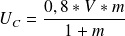
We consider that the protection of people is granted if the length of the feeder is less than
 calculated
Example :
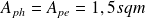
A resistive load with a current rating of 9A is supply by a 100m, 3 core, 1,5 sqm copper cable. The protection is ensure by a MCB 10A type C. The maximum contact voltage is

 With
With

 so
so

MCB is Type C so
 So
So

The Contact voltage is
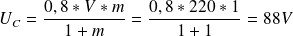
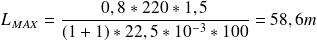
The contact voltage is dangerous (88V>50V) The maximum length must be 58,6m or the feeder of the load is 100m. THE PROTECTION OF THE PEOPLE IS NOT ENSURED!
To ensure the protection of the people in this situation, in case of insulation fault in the equipment, we must change the characteristics of the circuit:
Change the size of the wires (Costly)
Change the type of MCB (Type B)
Use RCD (Only in TNS!)


