Simplified method 2: Method of Impedances
Definition :
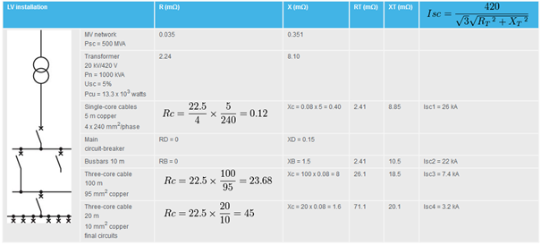
In a 3-phase installation Isc (the short circuit current) at any point is given by:

 = phase-to-phase voltage of the open circuited secondary windings of the power supply transformer(s).
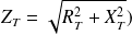
 = total impedance per phase of the installation upstream of the fault location (in Ω)
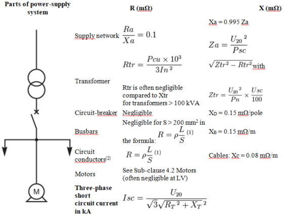
The method consists in dividing the network into convenient sections, and to calculate the R and X values for each. Where sections are connected in series in the network, all the resistive elements in the section are added arithmetically; likewise for the reactances, to give
 and
and
 . The impedance (
) for the combined sections concerned is then calculated from
. The impedance (
) for the combined sections concerned is then calculated from
Determination of the impedance of each component
Network upstream of the MV/LV transformer
The 3-phase short-circuit fault level
 , in kA or in MVA is given by the power supply authority concerned, from which an equivalent impedance can be deduced.
A formula
 which makes this deduction and at the same time converts the impedance to an equivalent value at LV is given, as follows:
 = impedance of the MV voltage network, expressed in milli-ohms
 = phase-to-phase no-load LV voltage, expressed in volts
 = MV 3-phase short-circuit fault level, expressed in kVA
Transformers
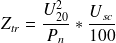
The impedance Ztr of a transformer, viewed from the LV terminals, is given by the formula:
-
= open-circuit secondary phase-to-phase voltage expressed in volts
 = rating of the transformer (in kVA)
 = the short-circuit impedance voltage of the transformer expressed in %
The transformer windings resistance R_{tr} can be derived from the total losses as follows:
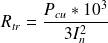
 = total losses in watts
 = nominal full-load current in amps
 = resistance of one phase of the transformer in milli-ohms (the LV and corresponding MV winding for one LV phase are included in this resistance value).
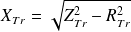
For an approximate calculation Rtr may be ignored since X ≈ Z in standard distribution type transformers. but the real value of the reactance is given by the formula
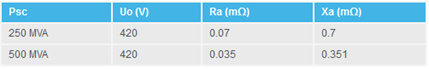
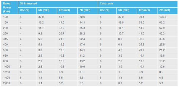
Resistance, reactance and impedance values for typical distribution 400V transformer with MV winding

Circuit-breakers
In LV circuits, the impedance of circuit-breakers upstream of the fault location must be taken into account. The reactance value conventionally assumed is 0.15 mΩ per CB, while the resistance is neglected.
Busbars
The resistance of busbars is generally negligible, so that the impedance is practically all reactive, and amounts to approximately 0.15 mΩ/metre (For 50 Hz systems, but 0.18 mΩ/m length at 60 Hz) length for LV busbars (doubling the spacing between the bars increases the reactance by about 10% only).
Circuit conductors
The resistance of a conductor is given by the formula:

ρ = the resistivity constant of the conductor material at the normal operating temperature being:
22.5 mΩ.mm2/m for copper
36 mΩ.mm2/m for aluminium
L = length of the conductor in m
A = Cross section of conductor in mm2
Cable reactance values can be obtained from the manufacturers. For Cross section of less than 50 mm2 reactance may be ignored. In the absence of other information, a value of 0.08 mΩ/metre may be used (for 50 Hz systems) or 0.096 mΩ/metre (for 60 Hz systems). For prefabricated bus-trunking and similar pre-wired ducting systems, the manufacturer should be consulted.
Motors
At the instant of short-circuit, a running motor will act (for a brief period) as a generator, and feed current into the fault. In general, this fault-current contribution may be ignored. However, if the total power of motors running simultaneously is higher than 25% of the total power of transformers, the influence of motors must be taken into account. Their total contribution can be estimated from the formula: Iscm = 3.5 In from each motor i.e. 3.5 m In for m similar motors operating concurrently. The motors concerned will be the 3-phase motors only; single-phase-motor contribution being insignificant.
Fault-arc resistance
Short-circuit faults generally form an arc which has the properties of a resistance. The resistance is not stable and its average value is low, but at low voltage this resistance is sufficient to reduce the fault-current to some extent. Experience has shown that a reduction of the order of 20% may be expected. This phenomenon will effectively ease the current-breaking duty of a CB, but affords no relief for its fault-current making duty.
Example : Recap
-
: Phase-to-phase no-load secondary voltage of MV/LV transformer (in volts).
-
: 3-phase short-circuit power at MV terminals of the MV/LV transformers (in kVA).
-
: 3-phase total losses of the MV/LV transformer (in watts).
 : Rating of the MV/LV transformer (in kVA).
 : Short-circuit impedance voltage of the MV/LV transformer (in %).
-
: Total resistance. XT: Total reactance
(1) ρ = resistivity at normal temperature of conductors in service
ρ = 22.5 mΩ x mm2/m for copper
ρ = 36 mΩ x mm2/m for aluminium
(2) If there are several conductors in parallel per phase, then divide the resistance of one conductor by the number of conductors. The reactance remains practically unchanged.